LocalWiki is a grassroots effort to collect, share and open the world's local knowledge
Explore LocalWiki
A community knowledge commons
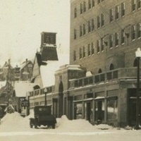
What if there was somewhere you could go to learn all about where you live? A place to learn about your neighborhoods, about your local parks, about being a parent in your city, about history, politics – anything and everything useful and beautiful about your community. With LocalWiki, everybody has a way to share and learn about where they live.
A collaborative storytelling tool
Whether it's knowing about butterfly corridors or the history of a local beach, everyone holds a piece of the puzzle of what it's like to live in their community. And unlike a news site or a blog, anyone can add and modify LocalWiki pages. LocalWiki lets you and your neighbors tell the story of your community, together.
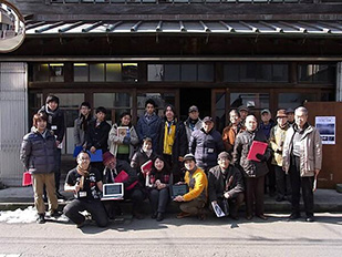
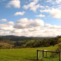
A global effort
From Sapporo, Japan to Oakland, California, communities across the world use LocalWiki to share their local knowledge. Learn about the issues that affect nearby communities, and communities halfway across the globe. There is a whole world to discover!

Free, open and non-profit
Like a park or a public library, LocalWiki is a public good. LocalWiki is free for anyone to read, copy and reuse for any purpose, and the backend code powering LocalWiki is open-source. We do not run any advertisements, and we are a 501(c)(3) non-profit organization. You can donate to support LocalWiki here.
An API for your city
LocalWiki represents a free, universally-accessible collection of the world's local knowledge upon which we hope countless civic and locally-relevant applications will be built. Our geospatially-aware, read-write API makes it easy to integrate LocalWiki with your application, or to import useful local data from elsewhere!
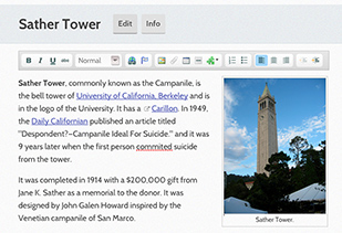
It's easy!
Adding to LocalWiki is as easy as making a Facebook post – contributing requires no technical knowledge or academic background. We have no complicated rules for how to format a page, or even what to write about: if it's useful or beautiful to your community, then it's worth sharing!
Recent blog posts
-
Thank you, Shuttleworth Foundation & Mapbox
 We would like to take a moment to thank the Shuttleworth Foundation, and Shuttleworth Fellow Rory Aronson, for their generous “flash grant” gift to LocalWiki! The Shuttleworth Foundation is a charitable foundation dedicated to furthering openness — open source, open ...
 -
LocalWiki Global Launch!
 From Sapporo, Japan to Oakland, California, people around the world use LocalWiki to share and learn about their local communities. Now, after much experimenting and development, we’re excited to announce the official, global launch of the LocalWiki project! #check_it_out { ...
 -
An API for your city
 We're excited to announce that the first version of the LocalWiki API has just been released! What's this mean? In June, folks in Raleigh held their annual CityCamp event. CityCamp is a sort of "civic hackathon" for Raleigh. During one ...
 -
San Francisco LocalWiki gentrification editathon
 Several editors on Saturday afternoon at the Prelinger Library. On Wednesday and Saturday of last week, contributors to the San Francisco LocalWiki held an editathon focusing on gentrification and displacement in SF: Do you often wonder what historical precedents have ...
LocalWiki is a grassroots effort to collect, share and open the world’s local knowledge. We are a 501(c)3 non-profit organization.


Except where otherwise noted, this content is licensed under a Creative Commons Attribution License. See Copyrights.
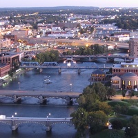
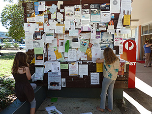
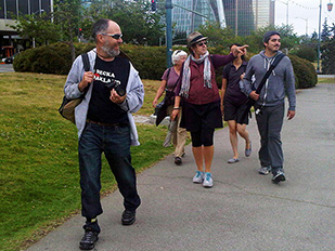
Map data © OpenStreetMap contributors. Map tiles via © MapTiler. Bridge photo CC-BY Stuart Seeger. Janes Walk photo by HiMY SYeD. Notice board photo CC-BY-SA-NC Bettina Walter.
Supported by
![]()
and people like you.